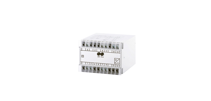
Description
DIN rail mounting transducers available in 55mm x 112mm or 100 x 112mm DIN rail cases
Application
Used to convert various inputs into standard DC signals for driving panel meters and for use in control devices.
Selection Guide
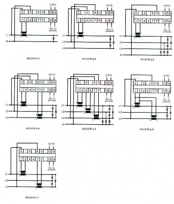
| M100-WA1 | Single Phase |
| M100-WA2 | 3 phase 3 wire balanced load |
| M100-WA3 | 3 phase 4 wire balanced load |
| M100-WA4 | 3 phase 3 wire unbalanced |
| M100-WA5 | 3 phase 4 wire unbalanced load |
| M100-WA6 | 3 phase 3 wire balanced load externally connected |
| reverse CT’S |
Typical Applications
The M100-WA series measures active power in single, 3 phase 3 or 4 wire balanced and unbalanced systems. Using the time division multiplier circuit means that they can be used over a wide range of input waveforms. The D.C. Output signal is directly proportional to the instantaneous power being measured. Typical applications include the measurement of power in switchboards, power stations, generating sets.
Technical Specifications
| INPUT | |
| Rated value In | 1 or 5 amp C.T. connected 0.5-10A direct |
| connected. |
| Rated value Un | 57.8 < 600 volt |
| Power Consumption | <1VA voltage <0.2VA current |
| Working Range | 0-125% Un auxiliary powered 75%-125% |
| self powered 0-150% In |
| Rated Frequency | 50/60/400Hz |
| Frequency Influence | 0.005% Hz |
| Overload Continuous | 4 x In 1.5 x Un |
| Overload for 1 sec | 50 x In 2 x Un |
| OUTPUT | |
| Rated value mA | 0-1/5/10/20 & 4-20mA |
| Rated value volts | 0-5/10 & 1-5V |
| ADJUSTMENT | |
| Zero | ±2% |
| Span | ±10% |
| AUXILIARY | |
| A.C. Voltage | 115/230/400V(±25%/45-65Hz/<2VA) |
| D.C. Voltage | 24/48/110V(±20%/galvanically isolated/<3W) |
| WEIGHT&CASE SIZE | |
| M100-WA1,2,3,6,7 | Approx 0.6kg. 100mm case |
| M100-WA4,5 | Approx 0.8kg. 100mm case |
Ordering Information
| Product Code | Input In | Un | O/P | Range | Aux | Freq | Opt |
| M100-WA5 | 5A | 230V | 0-20mA | 600kW | 230V | 50Hz | |
Options
| 1 | Non standard Inputs/Outputs as far as technically viable |
| 2 | A.C. Auxiliary in range 57.7 to 450 volts |
| 3 | Calibration at nominal Hz 35….450Hz |
| 4 | Calibration at temperature other than 23ºC |
A.C. Current Connection Diagrams